

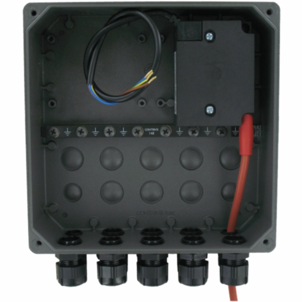

PARAMETRIC BURNER CONTROLLER

Q28 – PARAMETRIC BURNER CONTROLLER
• Supports natural and forced draught gas burners.
• Blue flame oil burners.
• Hydrogen burners.
• Single stage burners.
• Multi-stage burners.
• Flameless operation.
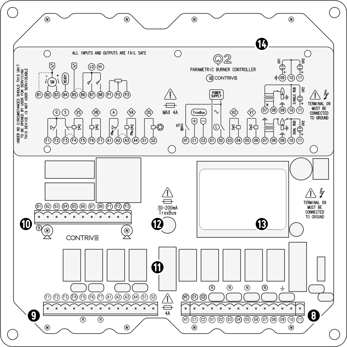
• Permanent operation.
• Air pressure switch.
• Fuel pressure switch.
• Proof of closure input.
• Up to 4 fuel valves.
• Air valve or blower output.
• Valve proving system (tightness control).
• Flame detection by means of UV sensor, dual or single electrode.
• Optional 2nd UV flame detector.
• Optional independent main flame supervision.
• Independent and configurable flame sensitivity.
• Electro-optical shutter control.
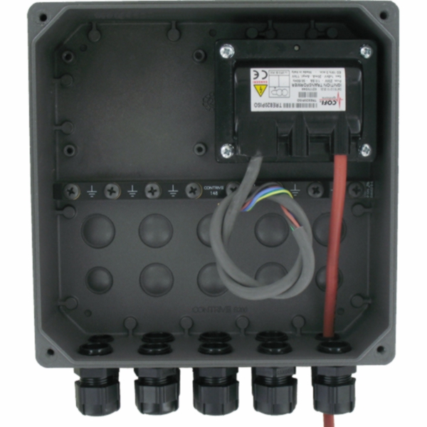
• Ignition transformer can be housed inside.
• 3 points actuator with preset positions and remote modulation control.
• High-temperature mode for indirect flame surveillance and flameless operation.
• Built-in fieldbus control, IIoT ready.
• Front magneto-optic jack for configuration and commissioning.
• LED-bar flame signal indicator.
• Advanced self-diagnostic report of cycle status, lockouts and failures.
• Log memory for lockouts, faults + unit and valves operating time.
• Safety Integrity Level - SIL3 – Systematic Capability - SC3.
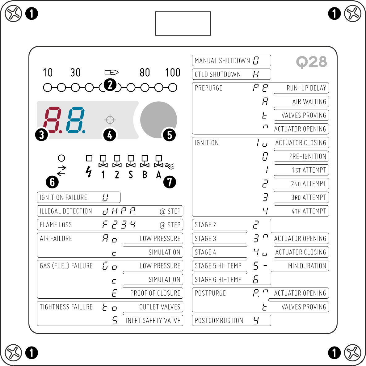
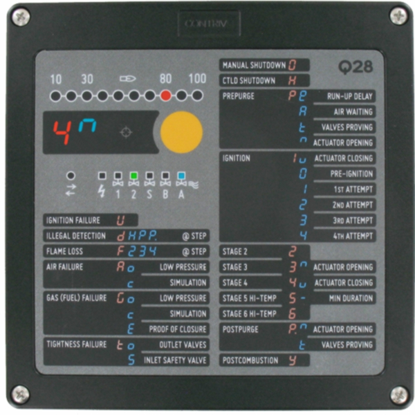
| FRONT PANEL | |
|---|---|
| M5 FITTING SCREWS | 1 |
| FLAME SIGNAL BARGRAPH | 2 |
| STATUS DISPLAY | 3 |
| OPTICAL INTERFACE | 4 |
| RESET / SHUTDOWN BUTTON | 4 |
| COM INDICATOR – YELLOW | 5 |
| OUTPUT INDICATORS | 7 |
| INTERNAL | |
|---|---|
| 8 | MAIN TERMINAL BOARD |
| 9 | EXTENDED TERMINAL BOARD |
| 10 | ACTUATOR TERMINAL BOARD |
| 11 | POWER SUPPLY FUSE 1 |
| 12 | TraxBus FUSE |
| 13 | IDENTIFICATION LABEL |
| 14 | PROTECTIVE COVER |
1 ULTIMATE PROTECTION AGAINST DANGEROUS CONDITIONS BY MEANS OF
INTERNAL NON REPLACEABLE 8A SAFETY FUSE
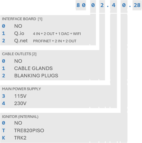
ORDER CODE
DEFAULT CONFIGURATION PROVIDED
SEND US YOUR DEFINED CONFIGURATION IF YOU WANT IT PRE-INSTALLED
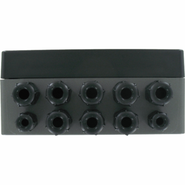
ELECTRICAL CONNECTIONS ARE MADE THROUGH CONNECTORS POSITIONED INSIDE THE UNIT
THE ENTIRE EQUIPMENT IS HOUSED IN THE UPPER SECTION
AND CAN BE REPLACED EASILY AND QUICKLY
PROVIDE RELIABLE CONNECTION TO PE (PROTECTION EARTH) AND BURNER FRAME
RECOMMENDED WIRE GAUGE > 4 mm2
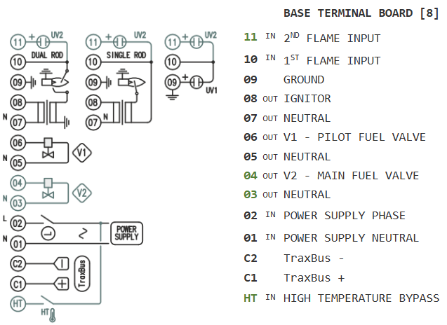
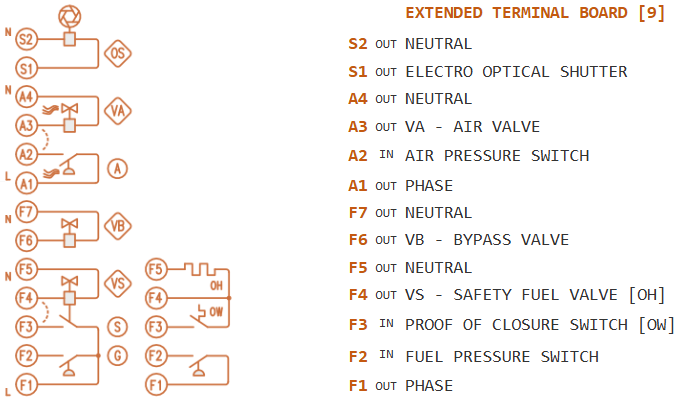
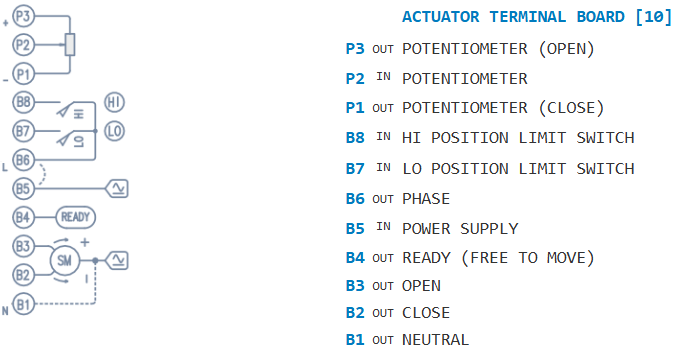
| EXTERNAL LIMITS | L |
|---|---|
| 1ST STAGE FUEL VALVE | V1 |
| 2ND STAGE FUEL VALVE | V2 |
| ACTUATOR (DAMPER) | SM |
| LO POSITION LIMIT SWITCH | LO |
| HI POSITION LIMIT SWITCH | HI |
| G | FUEL PRESSURE SWITCH |
|---|---|
| S | PROOF OF CLOSURE SWITCH |
| VS | SAFETY FUEL VALVE |
| VB | MULTIFUNCTIONAL BYPASS VALVE |
| A | AIR PRESSURE SWITCH |
| VA | AIR VALVE (BLOWER) |
| OS | ELECTRO-OPTICAL SHUTTER(S) |
Power supply
- • Voltage115 or 230 V +10-15%
- • Frequency50/60 Hz
- • Line FuseSLOW 4 A
- • Power Consumption< 10 VA
Environment
- • Operating Temperature-20...+60°C
- • Storage Temperature-40...+85°C
- • Umidità< 95% NO CONDENSATION
- • Protection ClassIP67 / NEMA4
- • WeightAPPROX 2000 g
- • Mounting Position ANY
Process Inputs
- • Current<3 mA
- • Response time< 1 s
Outputs
- • Max rated Voltage250 VAC
- • Max switching Voltage440 VAC
- • Max Load (per output)2 A PF=70%
TraxBus Com Interface
- • Voltage< 30 VDC
- • Baud Rate4800, 9600, 19200, 38400
Flame input 1
- • Minimum ionization Current> 1 μA
- • Current limitation< 3 mA
- • Sensor voltage250 V
- • Signal display0…100% | 0...30 μA
- • Sensor typeELECTRODE & UV
- • Sensor Line Length< 30 m
- • Single Rod Line Length< 2 m
Flame input 2
- • Minimum ionization Current> 1 μA
- • Current limitation< 3 mA
- • Sensor voltage250 V
- • Signal display0…100% | 0...30 μA
- • Sensor typeUV
- • Sensor Line Length< 30 m
Actuator
- • Max switching voltage300V
- • Max load per output< 4 A @ 250 VAC
- 2 A @ 30 VDC
- • Limit switches voltage115 or 230 V
- • Limit switches current<3 mA
- • Potentiometer voltage5 VDC
- • Potentiometer resistance 100…10000 Ω
- • Potentiometer line length< 3 m
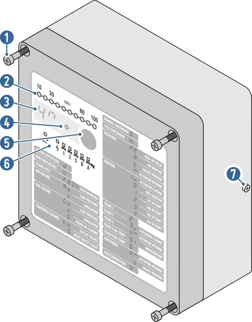
| LOCKING SCREWS - M5 | 1 |
|---|---|
| FLAME SIGNAL BARGRAPH | 2 |
| STATUS DISPLAY | 3 |
| OPTICAL INTERFACE | 4 |
| 5 | RESET / SHUTOFF BUTTON |
|---|---|
| 6 | OUTPUT INDICATOR LIGHTS |
| 7 | GROUND SCREW - M5 |
|
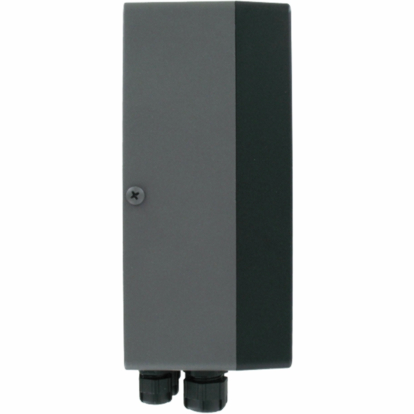
OVERALL DIMENSION: 200 x 120 x 71 mm |
|
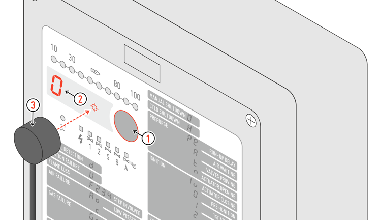
Q28 is fully configurable: the same device can be used to control different types of gas and oil burners. Password is required to modify all parameters except for Communication settings.
To change the device configuration:
1 ► Press the front button to force the MANUAL SHUTDOWN.
2 ► Display code 0 confirm that current status is MANUAL SHUTDOWN
3 ► Put the optical jack on the crosshairs between the display and the key
3 ► the internal magnet will hold it in place.
Connect the optical jack Q.link to a USB port on PC and start Q.Suite software.
All parameters can be read, but modification is password protected (factory default 00000000). The default password cannot be confirmed and must be changed upon first configuration.
Note on EC type-examination
Since EN 298 does not describe all functions of the Q28 – implemented to manage all possible industrial scenarios – the operator is responsible for ensuring that parameters and functions are appropriate for the application.
Certification applies only for options and values allowed by EN-298.