


Electronic high frequency
Ignition transformer
for gas and oil burners
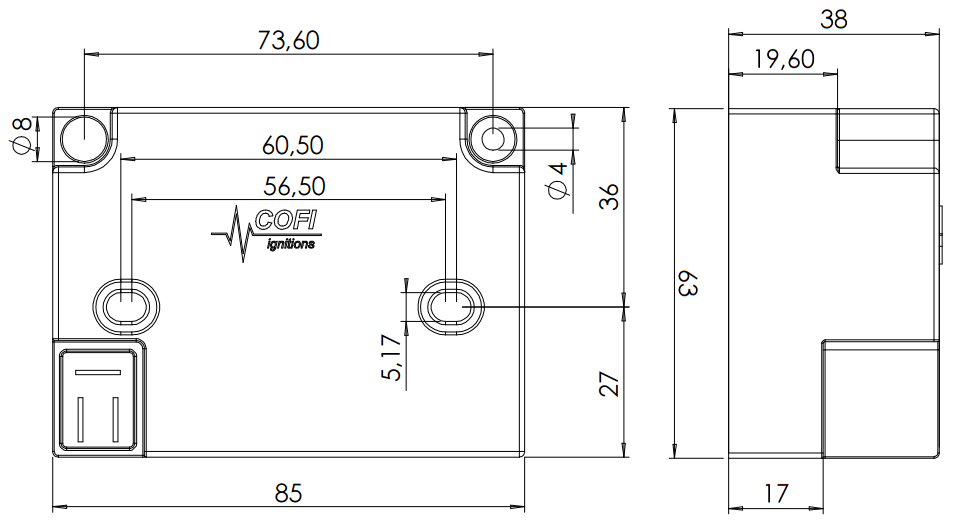
TRK2 – Compact lightweight ignition transformer
Ignition transformer designed for gas and oil burners with smaller size and weight than conventional inductive transformers.
The unit is vacuum impregnated to ensure the highest rate of insulation.
Transformer without EMC filter, suitable for single rod operation. Switchover between ignition and flame detection is performed by the burner control unit.
POWER SUPPLY INLET
Plug D
vertical 3 poles
HI VOLTAGE OUTLET
Vertical plug Ø 4 mm
13,5 mm deep
| ORDER CODE | DESCRIPTION | NOTE |
|---|---|---|
| 1830.40.00 |
TRK2 230VAC Electronic ignition transformer – 230Vac |
ACTIVE |
| 1830.30.00 |
TRK2 115VAC Electronic ignition transformer – 115Vac |
ACTIVE |
| 1830.00.01 |
TRK2 POWER SUPPLY CABLE Overmolded cable with Plug D – 30+7 mm |
ACTIVE |
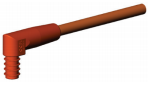
| 1840.01.01 |
HI VOLTAGE CABLE 1300mm | 2 plugs Silicone/Copper 1mm2 20kV -50 +180°C Overmolded 4mm plug – 6.3mm rod plug 90° |
ACTIVE |
| 1840.01.02 |
HI VOLTAGE CABLE 1800mm | 2 plugs Silicone/Copper 1mm2 20kV -50 +180°C Overmolded 4mm plug – 6.3mm rod plug 90° |
ACTIVE |
Use unscreened high-voltage cable for the ignition cable: the spark intensity is lower when using a screened cable.
Keep the ignition cable as short as possible: the longer the ignition cable, the lower the spark intensity and greater the generated electrical interferences.
Plugs with integrated 1 kΩ resistor could be optionally used to reduce radio interferences.
A reliable connection to ground must be provided for the transformer and the burner frame, recommended wire gauge > 4 mm2.
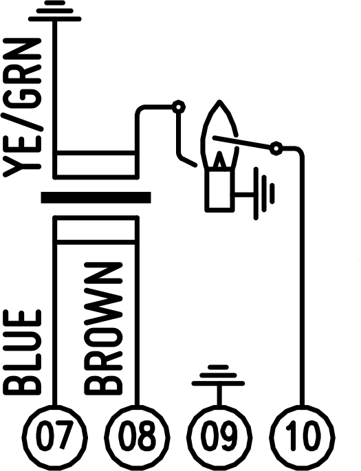
2 INDEPENDENT RODS |
|---|
|
BLUE WIRE NEUTRAL QBK TERMINAL 07 |
|
BROWN WIRE PHASE QBK TERMINAL 08 |
|
YELLOW GREEN WIRE SECONDARY RETURN CONNECTED TO GROUND |
The high voltage creates a spark between the ignition electrode and burner ground.
The flame current flows from the dedicated electrode into the control unit.
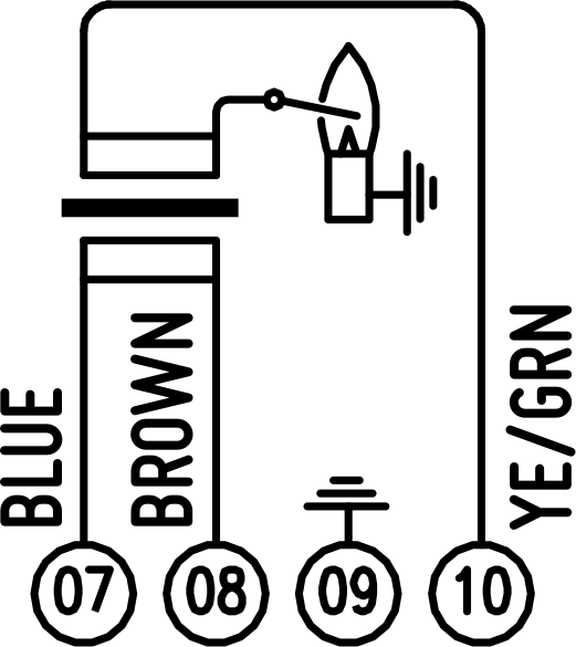
1 SHARED ROD |
|---|
|
BLUE WIRE NEUTRAL QBK TERMINAL 07 |
|
BROWN WIRE PHASE QBK TERMINAL 08 |
|
YELLOW GREEN WIRE SECONDARY RETURN QBK TERMINAL 10 |
A single electrode used for both ignition and flame detection.
Electrode switched to ground during the ignition. The flame current flows from the electrode through the secondary winding into the control unit.
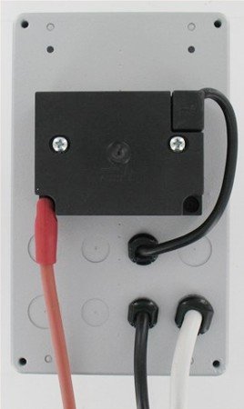
EASY TO FIT
Two holes for self tapping screws are available to install the ignition transformer directly on the back of the QBK enclosure.
The high voltage cable is fully accessible without opening the box.
Eight breakable holes for strain reliefs or glands are available for cables exit.
Using this solution the accessible front is clean and it's possible to install several controls side by side.
- • Primary Supply Voltage220 … 240 VAC
- 110 … 120 VAC
- • Primary Supply Current< 275 mA @ 230V
- < 550 mA @ 115V
- • Frequency50 … 60 Hz
- • Power63 W
- • Secondary Peak Voltage 115 kV ±10%
- • Secondary Current 230 mA RMS
- • Minimum Secondary Current 320 mA RMS
- • Duty cycle33% 3 minutes
- • EnclosurePBT filled with Epoxy resin
- • Operating Temperature-20 … +60°C
- • Storage Temperature-20 … +85°C
- • Protection ClassIP00
- • Weight340 g
- • Ignition cable length< 2 m
- • Recommended spark gap3 … 5 mm
- • Mounting Position ANY
1 OPEN CIRCUIT
2 SHORT CIRCUIT
3 5 mm SPARK GAP, BLOWING AIR
The duty cycle indicates for how long the ignition transformer can operate within 180 s.
Max operating time = Duty cycle [%] × 180 s / 100%
Considering 33% duty cycle of TRK2, the maximum operating time is 60 s within 3 minutes.
This means a maximum of 4 ignitions of 5 seconds each are allowed per minute without damages.