


Protocol converter from TraxBus to PROFIBUS-DP
Up to 100 burners in a single Profibus-DP node
No costly Profibus-DP connectors
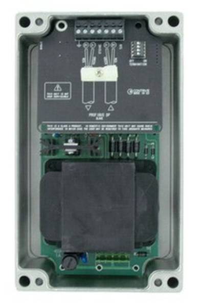
TraxGateway connects TraxBus to a standard field network using the PROFIBUS-DP protocol.
PROFIBUS-DP is included into the European Fieldbus Standard EN 50170.
The network is primarily used in process and factory automation.
By installing the TraxGateway it is possible to monitor and operate remote Burner Control Units QBK and QUAD from a PROFIBUS-DP master device.
TraxGateway transfers the control signals received from control system (PLC) to peripherals. In the opposite direction it holds all peripherals operating status.
A complete galvanic isolation is provided between all the section of the TraxGateway.
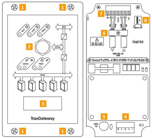
| FRONT PANEL | |
|---|---|
| FITTING SCREWS | 1 |
| SEALED MINI USB CONNECTOR | 2 |
| DISPLAY | 3 |
| INTERNAL | |
|---|---|
| 4 | MAIN TERMINAL BOARD |
| 5 | POWER SUPPLY FUSE |
| 6 | PROFIBUS SHILED CLIP |
| 7 | PROFIBUS TERMINAL BOARD |
| 8 | PROFIBUS TERMINATION SWITCH |
| ORDER CODE | DESCRIPTION | NOTE |
|---|---|---|
| 1360.30.04 |
TraxGateway PDP 115 N Gateway TraxBus › Profibus DP • 115 Vac |
ACTIVE |
| 1360.40.04 |
TraxGateway PDP 230 N Gateway TraxBus › Profibus DP • 230 Vac |
ACTIVE |
The PROFIBUS-DP connector is a 7 pin screw terminal 2,5 mm2 (AWG14).
Cable shield MUST be connected to specific pin or metallic tab under the retaining clip. An optional connection to next slave is available.
A low-impedance connection to Protective Earth MUST be provided using a cable crossection as large as possible in order to consistently shield the bus.
Power supply and TraxBus connector is a 5 pin screw terminal 2,5 mm2 (AWG14).

| POWER SUPPLY – NEUTRAL | N |
|---|---|
| POWER SUPPLY – PHASE | L |
| PROTECTIVE EARTH | G |
| + | TRAXBUS – POSITIVE |
|---|---|
| – | TRAXBUS – NEGATIVE |
Power Supply
- • Voltage115 or 230 V +10-15%
- • Frequency50/60 Hz
- • Line Fuse1 A
- • Power Consumption< 35 VA
- • Terminals3x2,5 mm2
Environment
- • Operating Temperature-10 … +70°C
- • Storage Temperature-25 … +85°C MAX
- • Protection ClassIP64 / NEMA3
- • Relative Humidity5 … 95% A
- • WeightAPPROX 1600 g
- • Mounting Position ANY
- A NON CONDENSING
Active TraxBus Interface
- • TypeASYN MULTIDROP HALF DUPLEX
- • Peripherals120 MAX
- • Bus Voltage≤ 30VDC
- • Bus Current< 1,3A
- • Allowable Voltage Dropout< 3V
- • Allowable Line Capacitance< 100nF
- • Baud Rate38400 MAX
- • Terminals2x2,5 mm2
- • Communication speed 9600 … 12M bit/s B
- • Physical LayerRS485
- • Terminals7x2,5 mm2
- B AUTOMATIC DETECTION
Profibus-DP
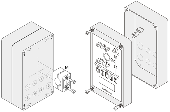
| EXTERNAL FITTING HOLES | 1 |
|---|---|
| BREAKABLE FITTING HOLES | 2 |
| BREAKABLE PG11 HOLES FOR WIRING | 3 |
| BREAKABLE PG9 HOLES FOR WIRING | 4 |
| M | OPTIONAL PIPE FITTING CLAMP |
|---|---|
| CAST ALUMINUM ALLOY EN AB 46100
OVERALL DIMENSION: 200 x 120 x 71 mm ELECTROSTATIC POLYESTER COATING COLOR: GRAY RAL9006 |
|
The Profibus communication cable must be kept away from any cable carrying electrical noise.
Use only PROFIBUS-DP dedicated communication cables.
TraxBus lines can be wired in any form: star, ring, straight or mixed. Do not use shielded cables.
| FROM MAIN POWER SUPPLY | 1 |
|---|---|
| FROM PROFIBUS MASTER | 2 |
| TO NEXT PROFIBUS SLAVE | 3 |
| USE MULTICORE CABLES (POWER SUPPLY + TraxBus) FOR SHORT STUBS ONLY |
