

Compare versions

The burner control unit QBK [cubic] is suitable for the control of pilot burners up to 350 kW and main burners of unlimited capacity, pursuant to EN 746-2, for intermittent or continuous operation.
Flame control by means of UV scanner or ionization rod (even shared with ignition) and high-temperature option for flame surveillance bypass.
Specific output for air valve or fan, following cycle or independently controllable.
Times and cycle are configurable: the same device can be used to control different types of gas, oil and mixed burners.
User interface providing a led-bar flame signal indicator, seven segment status display and reset/shutdown button. Remote control and supervision of the burner can be implemented by means of digital inputs/outputs or through serial communication.
The unit is integrated into an aluminum enclosure, available in 3 version:
| PLUS | FULL | BASIC | MINI | ||
| 1ST FUEL VALVE | Output for (pilot burner) fuel valve. | ✔ | ✔ | ✔ | ✔ |
| 2ND FUEL VALVE | Output for main burner fuel valve. | ✔ | ✔ | ✖ | ✖ |
| AIR OUTPUT | Output for blower or air valve. | ✔ | ✔ | ✖ | ✖ |
| AIR PRESSURE SWITCH | Input from low air pressure switch. | ✔ | ✔ | ✖ | ✖ |
| AIR ACTUATOR CONTROL | Output for servomotor control. | ✔ | ✖ | ✖ | ✖ |
| BURNER ON | Output activated when burner is running. | ✔ | ✔ | ✔ | ✖ |
| BURNER LOCKOUT | Output activated while in lockout. | ✔ | ✔ | ✔ | ✖ |
| REMOTE RESET | Input for reset from lockout. | ✔ | ✔ | ✔ | ✖ |
| REMOTE AIR CONTROL | Input for remote control of air output. | ✔ | ✔ | ✖ | ✖ |
| THERMOSTAT 1 | Input to start/stop the burner. | ✔ | ✔ | ✔ | ✖ |
| THERMOSTAT 2 | Input to start/stop the main burner. | ✔ | ✔ | ✖ | ✖ |
| HI-TEMP BYPASS | Input for indirect flame surveillance above 750°C. | ✔ | ✔ | ✖ | ✖ |
| 2ND FLAME SENSOR | Input for independent main flame sensor. | ✔ | ✔ | ✖ | ✖ |
| SUPPLY MONITOR | Protection against over/undervoltages. | ✔ | ✔ | ✔ | ✔ |
| TraxBus | Interface for communication fieldbus. | ✔ | ✔ | ✔ | ✔ |
| INFRARED | Local configuration/control with smartphone app. | ✔ | ✔ | ✔ | ✔ |
| DIAGNOSTIC | Display reports cycle, lockouts and failures. | ✔ | ✔ | ✔ | ✔ |
| LIFE COUNTER | Counter for ignition cycles and working times. | ✔ | ✔ | ✔ | ✔ |
| LOG MEMORY | Last 60 lockouts, failures and manual shutdowns. | ✔ | ✔ | ✔ | ✔ |
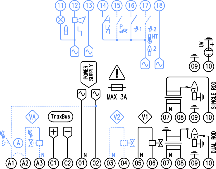
A1 • LOW AIR PRESS SWITCH INPUT
A2 • AIR VALVE OUTPUT – L
A3 • AIR VALVE OUTPUT – N
C1 • COM INTERFACE – POSITIVE
C2 • COM INTERFACE – NEGATIVE
01 • POWER SUPPLY – N
02 • POWER SUPPLY – L
03 • MAIN VALVE – N
04 • MAIN VALVE – L
05 • PILOT VALVE – N
06 • PILOT VALVE – L
07 • IGNITION TRANSFORMER – N
08 • IGNITION TRANSFORMER – L
09 • GROUND
10 • FLAME SENSOR INPUT
11 • OUTPUT BURNER ON
12 • OUTPUT BURNER LOCKOUT
13 • OUTPUTS COMMON
14 • INPUT RESET
15 • INPUT AIR CONTROL
16 • INPUT THERMOSTAT 1
17 • THERMOSTAT 2 | HI BYPASS | FLAME 2
18 • INPUTS COMMON
BLUE PARTS NOT AVAILABLE FOR MINI VERSION
DOTTED PARTS AVAILABLE FOR FULL VERSION ONLY
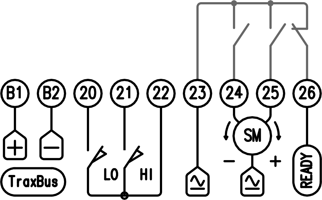
B1 • COM INTERFACE – POSITIVE
B2 • COM INTERFACE – NEGATIVE
20 • MIN POSITION LIMIT SWITCH
21 • MAX POSITION LIMIT SWITCH
22 • LIMIT SWITCHES COMMON RETURN
23 • ACTUATOR POWER SUPPLY PHASE
24 • ACTUATOR CLOSE OUTPUT
25 • ACTUATOR OPEN OUTPUT
26 • MODULATION READY OUTPUT
3 POINTS AIR SERVO ACUATOR (PLUS VERSION ONLY)
B1-B2 REPLACE THE ORIGINAL INTERFACE TERMINALS C1-C2

B1 • COM INTERFACE – POSITIVE
B2 • COM INTERFACE – NEGATIVE
20 • MIN POSITION LIMIT SWITCH
21 • MAX POSITION LIMIT SWITCH
22 • COMMON RETURN
23 • OUTPUT TO MOTOR SETPOINT
26 • INPUT FROM CONTROLLER
ANALOG AIR SERVO ACUATOR (PLUS VERSION ONLY)
0…10V | 0…20mA | 4…20mA