


BASIC VERSION
Automatic Burner Control Unit for gas and oil burners
Remote control through process inputs or fieldbus
Intermittent or continuous operation


QBK BASIC – 1 stage
• Natural or forced draught gas burners.
• Blue flame oil burners.
• Single stage burners.
• Flame detection by means of UV sensor, dual or single electrode.
• Burner ON output.
• Burner LOCKOUT output.
• Remote RESET input.
• THERMOSTAT input for remote burner control.
• Built-in fieldbus control.
• Infrared commissioning interface (smartphone app).
• Led-bar flame signal indicator.
• Independent and configurable flame sensitivity for pilot and main burners.
• Advanced self-diagnostic report of cycle status, lockouts and failures.
• Log memory for lockouts and faults.

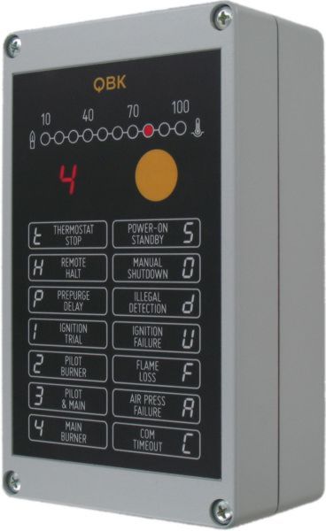
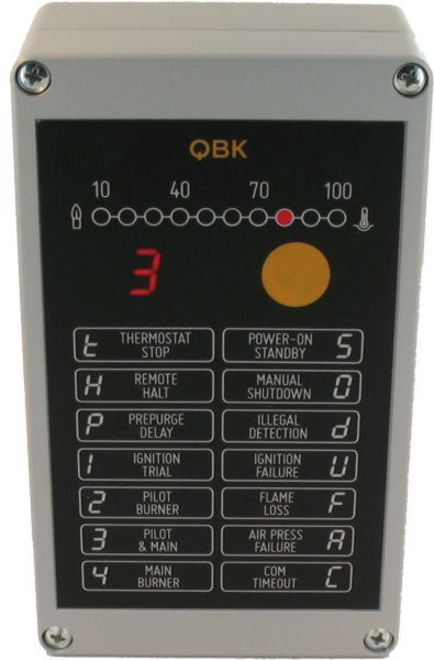
| FRONT PANEL | |
|---|---|
| FITTING SCREWS | 1 |
| FLAME SIGNAL BARGRAPH – RED | 2 |
| STATUS DISPLAY | 3 |
| RESET / SHUTOFF BUTTON | 4 |
| COM INDICATOR – YELLOW | 5 |
| AIR OUTPUT INDICATOR – BLUE | 6 |
| HI-TEMP BYPASS INDICATOR – RED | 7 |
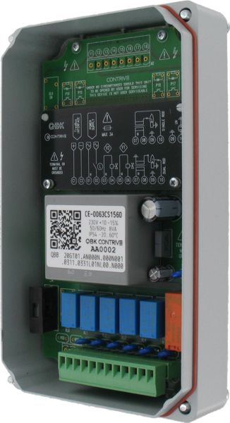
| INTERNAL | |
|---|---|
| 8 | MAIN TERMINAL BOARD |
| 9 | POWER SUPPLY FUSE 1 |
| 10 | INPUT/OUTPUT TERMINAL BOARD |
| 11 | INPUT VOLTAGE SPECIFICATION |
| 1 | ULTIMATE PROTECTION AGAINST DANGEROUS CONDITIONS BY MEANS OF INTERNAL NON REPLACEABLE 5A SAFETY FUSE |

| ORDER CODE | DESCRIPTION | NOTE |
|---|---|---|
| 1488.33.PB |
QBK BASIC 115 PLASTIC Power supply 115V |
ACTIVE |
| 1488.44.PB |
QBK BASIC 230 PLASTIC Power supply 230V |
ACTIVE |
| 1488.33.0B |
QBK BASIC 115 ALUMINIUM Power supply 115V |
ACTIVE |
| 1488.44.0B |
QBK BASIC 230 ALUMINIUM Power supply 230V |
ACTIVE |
ORDER CODE MUST BE COMPLETED WITH CONFIGURATION CODE
PROVIDE RELIABLE CONNECTION TO PE (PROTECTION EARTH) AND BURNER FRAME
RECOMMENDED WIRE GAUGE > 4 mm2
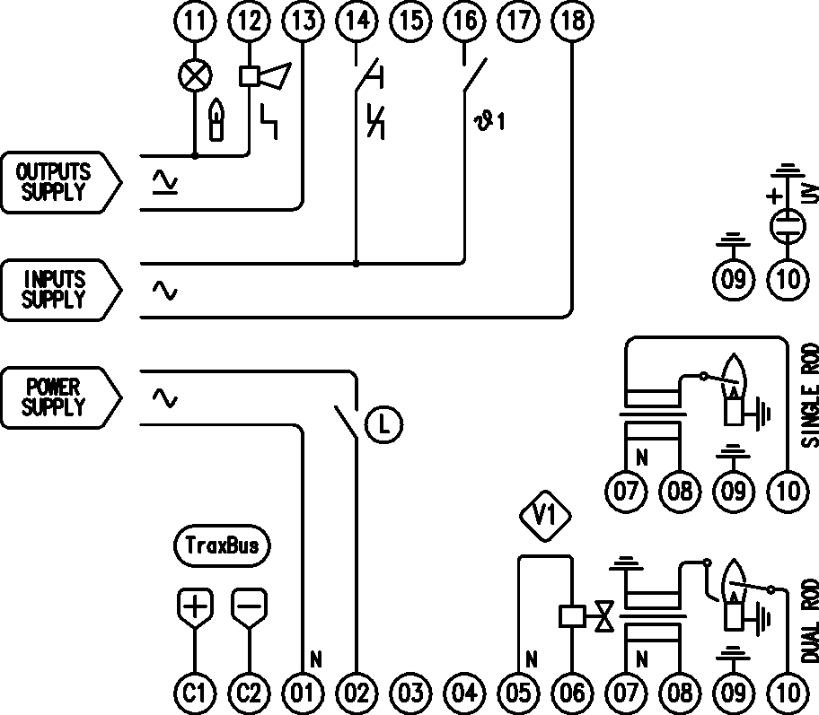
| COM INTERFACE – POSITIVE | C1 |
|---|---|
| COM INTERFACE – NEGATIVE | C2 |
| POWER SUPPLY – N | 01 |
| POWER SUPPLY – L | 02 |
| FUEL VALVE – N | 05 |
| FUEL VALVE – L | 06 |
| IGNITION TRANSFORMER – N | 07 |
| IGNITION TRANSFORMER – L | 08 |
| GROUND | 09 |
| FLAME SENSOR INPUT | 10 |
| 11 | ► OUTPUT BURNER ON |
|---|---|
| 12 | ► OUTPUT BURNER LOCKOUT |
| 13 | ► OUTPUTS COMMON |
| 14 | ◀ INPUT RESET |
| 16 | ◀ INPUT THERMOSTAT 1 |
| 18 | ◀ INPUTS COMMON |
| L | EXTERNAL LIMITS |
| V1 | FUEL VALVE |
Power supply
- • Voltage115 or 230 V +10-15%
- • Frequency50/60 Hz
- • Line FuseQUICK 3 A
- • Power Consumption< 6 VA
- • Power Dissipation< 4 W
Environment
- • Operating Temperature-20...+60°C
- • Storage Temperature-40...+85°C
- • Relative HumidityNO CONDENSATION
- • Protection ClassIP64 / NEMA3
- • WeightAPPROX 1100 g
- • Mounting Position ANY
Outputs
- • Max rated Voltage250 VAC
- • Max switching Voltage440 VAC
- • Max Load (per output)2 A PF=70%
Process Inputs
- • Rated Voltage230, 115, 48, 24 V
- • Current< 3 mA
Flame detection
- • Minimum ionization Current> 1 μA
- • Current limitation< 3 mA
- • Signal Display0...100% | 0...30 μA
- • Detector Line Length< 30 m
- • Single Rod Line Length< 2 m
- • Detector Voltage< 250 VAC
- • Detector Insulation> 50 MΩ
- • UV SensorUV4SH
TraxBus Com Interface
- • Voltage< 30 VDC
- • Baud Rate4800, 9600, 19200, 38400
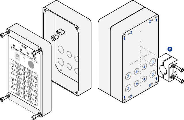
| EXTERNAL FITTING HOLES | 1 |
|---|---|
| BREAKABLE FITTING HOLES | 2 |
| BREAKABLE PG11 HOLES FOR WIRING | 3 |
| BREAKABLE PG9 HOLES FOR WIRING | 4 |
| M | OPTIONAL PIPE FITTING CLAMP |
|---|---|
| CAST ALUMINUM ALLOY EN AB 46100 or
THERMOPLASTIC POLYMER BLEND UL-V0
OVERALL DIMENSION: 200 x 120 x 71 mm EXTERNAL COATING GRAY RAL9006 |
|
QBK is fully confgurable: the same device can be used to control different types of gas and oil burners. Password is required to modify all parameters except for Communication settings.
GENERAL SETTINGS
001 • POWER SUPPLY VOLTAGE
002 • PROCESS INPUTS VOLTAGE
003 • BURNER TYPE
AT POWER ON – LOCKOUT
DURING SHUTDOWN
DURING PREPURGE
DURING IGNITION
401 • PRE-IGNITION TIME
402 • FIRST SAFETY TIME
403 • PILOT STARTUP ATTEMPTS
404 • PILOT FLAME SENSITIVITY
DURING OPERATION
501 • PILOT PROVING PERIOD
504 • FLAME FAILURE
505 • FLAME FAIL RESPONSE TIME
508 • MIN COMBUSTION TIME
509 • POST-COMBUSTION TIME
DURING POSTPURGE
COMMUNICATION SETTINGS
701 • ZONE (SEGMENT)
702 • UNIT (NODE)
703 • BAUD RATE
704 • TIMEOUT
Customers that want to modify the configuration can apply for specific agreement here. Once approved, all purchased units will have unique password assigned. Since a new label or remark must be placed on the unit when the original configuration is modified, this procedure is not recommended for occasional users.

Configuration code with default settings (red)
Note on EC type-examination
Since EN 298 does not describe all functions of the QBK – implemented to manage all possible industrial scenarios – the operator is responsible for ensuring that parameters and functions are appropriate for the application.
Certification applies only for options and values allowed by EN-298.