
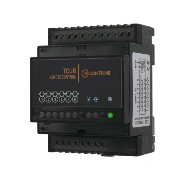
Remote Controller
TraxBus to digital I/O
Control up to 6 burner zones without PLC nor programming
TCU6 provides all the advantages of TraxBusTM fieldbus management, without the need for a PLC and therefore without programming.
SIX burners or zone of burners can be simply controlled with an electrical interface:
• INPUT from THERMOSTAT contact - start / stop the burner(s)
• OUTPUT contact BURNER ON - if at least one burner within a zone is running
For all burners connected:
• INPUT from UNLOCK button - reset all the burners in lockout
• OUTPUT contact LOCKOUT - if at least one of linked burners is in lockout
TCU6 is an expansion unit to be used together with TraxInterface4, connected to Service Port.
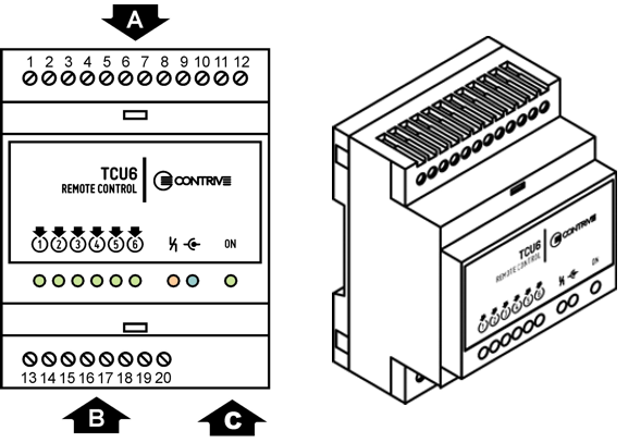
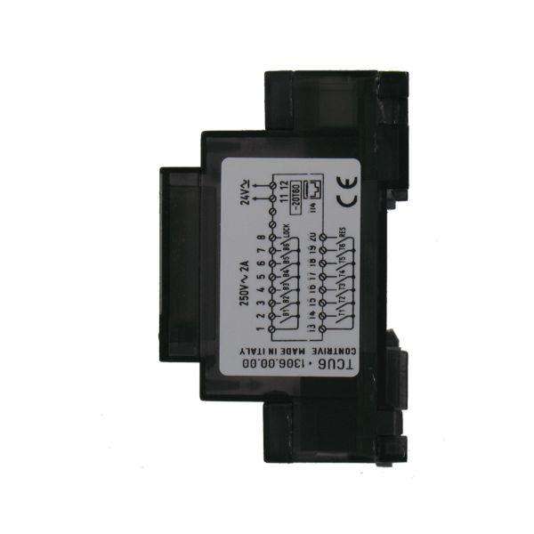
| OUTPUTS AND SUPPLY TERMINALS | A |
|---|---|
| INPUTS TERMINALS | B |
| C | RJ45 CONNECTOR TO TraxInterface4 |
|---|---|
| ORDER CODE | DESCRIPTION | NOTE |
|---|---|---|
| 1306.00.04 |
TCU6 6 zone TraxBus controller |
ACTIVE |
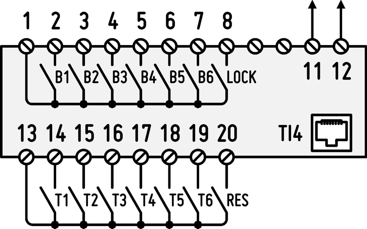
| OUTPUTS COMMON | 1 |
|---|---|
| OUTPUT ZONE 1 ON 1 | 2 |
| OUTPUT ZONE 2 ON 1 | 3 |
| OUTPUT ZONE 3 ON 1 | 4 |
| OUTPUT ZONE 4 ON 1 | 5 |
| OUTPUT ZONE 5 ON 1 | 6 |
| OUTPUT ZONE 6 ON 1 | 7 |
| OUTPUT LOCKOUT 2 | 8 |
| POWER SUPPLY | 11 |
| POWER SUPPLY | 12 |
| 13 | INPUTS COMMON |
|---|---|
| 14 | THERMOSTAT ZONE 1 INPUT 3 |
| 15 | THERMOSTAT ZONE 2 INPUT 3 |
| 16 | THERMOSTAT ZONE 3 INPUT 3 |
| 17 | THERMOSTAT ZONE 4 INPUT 3 |
| 18 | THERMOSTAT ZONE 5 INPUT 3 |
| 19 | THERMOSTAT ZONE 6 INPUT 3 |
| 19 | BURNERS UNLOCK INPUT 4 |
|
1 AT LEAST 1 BURNER ON (PER ZONE) 2 AT LEAST 1 BURNER IN LOCKOUT (ALL) 3 RUN/HALT BURNERS (PER ZONE) 4 RESET FROM LOCKOUT (ALL) |
|
Power Supply
- • Voltage24VAC / 30 VDC ±10%
- • Frequency0 … 200 Hz
- • Power consumption< 2 W
- • Isolation1000 VDC / 1s
- • Terminals2x2,5 mm2
OUTPUTS
- • Nominal Voltage250 VAC
- • Nominal Current3 A
- • Breaking Voltage277 VAC
- • Breaking Capacity750 VA
- • Minimum Contact Load1mA @ 5 VDC
- • Insulation (IEC60664)277 VAC
- • Surge Voltage5000 VRMS
- • Coil-Contact Dilectric Strength3000 VRMS
- • Open Contact Dilectric Strength750 VRMS
- • Terminals8x2,5 mm2
INPUTS
- • Voltage5 VDC
- • Current< 5 mA
- • Terminals8x2,5 mm2
Link Port
- • TypeSYNCHRONOUS HALF DUPLEX
- • ConnectorMODULAR JACK RJ45
Environment
- • Operating Temperature-20 … +60 °C
- • Storage Temperature-40 … +85 °C MAX
- • EnclosureUL94-V0
- • Protection ClassIP20
- • Relative Humidity30 … 90% 1
- • Dimensions71 × 90 × 58 mm
- • Mounting Position ANY
1 NON CONDENSING
2 ZONE EXAMPLE
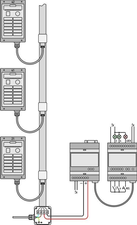
This application manages 3 burner controllers: one unit only is belonging to zone 2 and two units belonging to zone 4.
It is possible to have up to 250 units assigned to up to 6 zones.
Set the address of remote units, assigning at least the zone identifier (the unit identifier could be different or the same for all units belonging to a zone).
The address of the devices can be easily assigned using either QUID or Q|beam.
|
Burner having address 21 is controlled by input contact 2. Close to start and open to stop the burner, behavior similar to a thermostat. Any other burner controller whose zone address is 2 will be controlled. |
|
Output 2 turns on when burner 21 is running. Any other burner controller whose zone address is 2 will turn on the pilot lamp, if running. |
|
Burner 41 and 42 are controlled by input contact 4. Close to start and open to stop the burner, behavior similar to a thermostat. Any other burner controller whose zone address is 4 will be controlled. |
|
Output 4 turns on when at least one burner belonging to zone 4 (41 and 42) is running. Any other burner controller whose zone address is 4 will turn on the pilot lamp, if running. |
|
Output LOCK turns on when there is one or more burners in LOCKOUT. Any burner controller in the network will turn on the pilot lamp, if in lockout. |
|
Close input RES for a while to RESET all the burners currently in lockout. Reset will take place when input is released. Any burner controller in the network that is currently in lockout will restart. QBK limits the maximum number of resets to 5 actions within a span of 15 minutes. |