|
COVER BAYBLEND® FR3010 - PC+ABS INCREASED HEAT RESISTANCE |
|||||||||||||||||||||
|
|
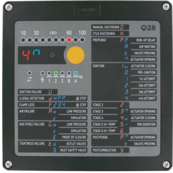
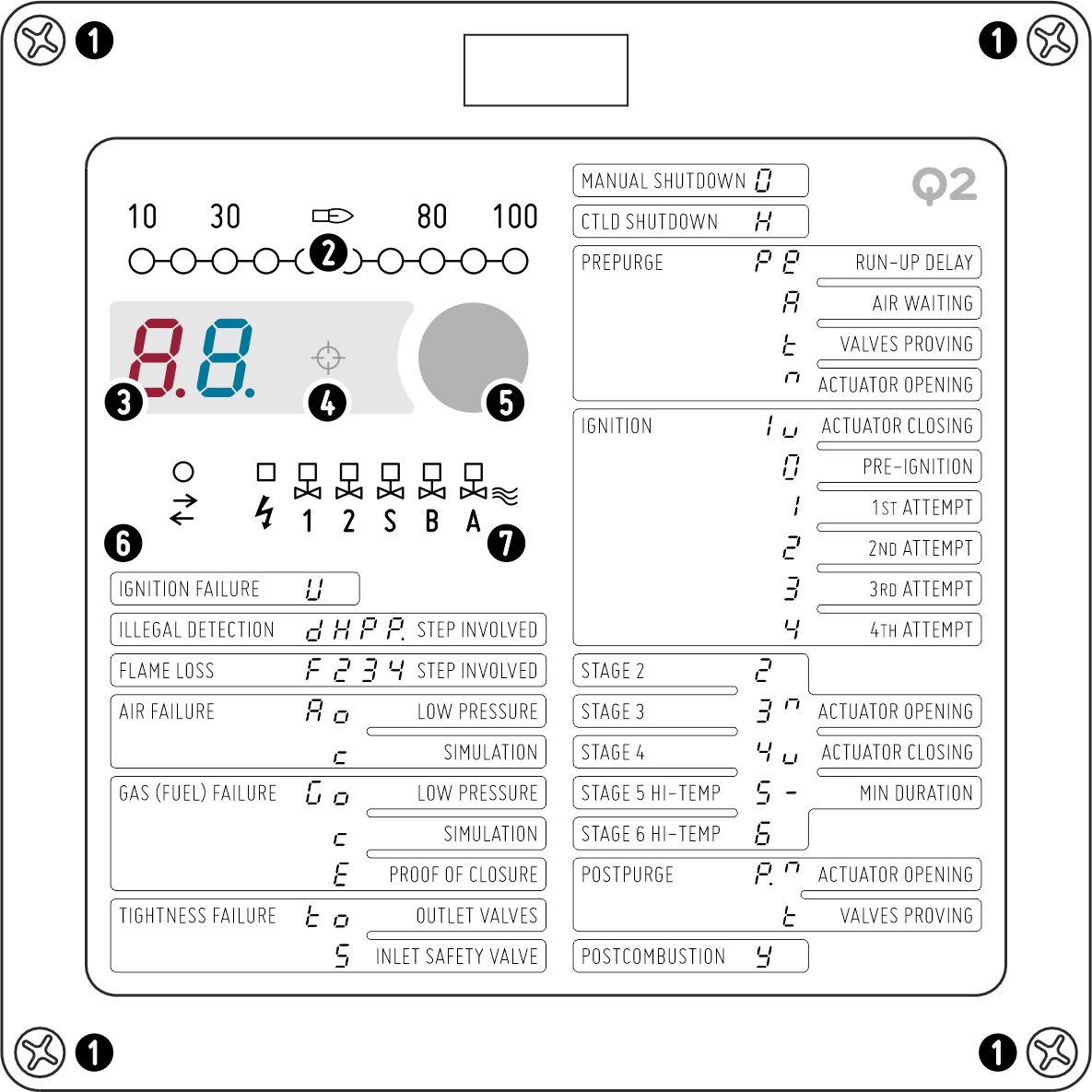
FRONT PANEL 1 M5 FITTING SCREWS 2 FLAME BAR GRAPH 3 STATUS DISPLAY 4 OPTICAL INTERFACE 5 RESET/SHUTDOWN BUTTON 6 COM INDICATOR 7 OUTPUT INDICATORS |
||||||||||||||||||||
|
To ensure an IP67 degree of protection, the 4 screws [1] must be tightened with a tightening torque of approximately 1.5 Nm. |
|||||||||||||||||||||
|
|
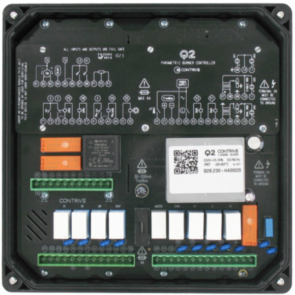
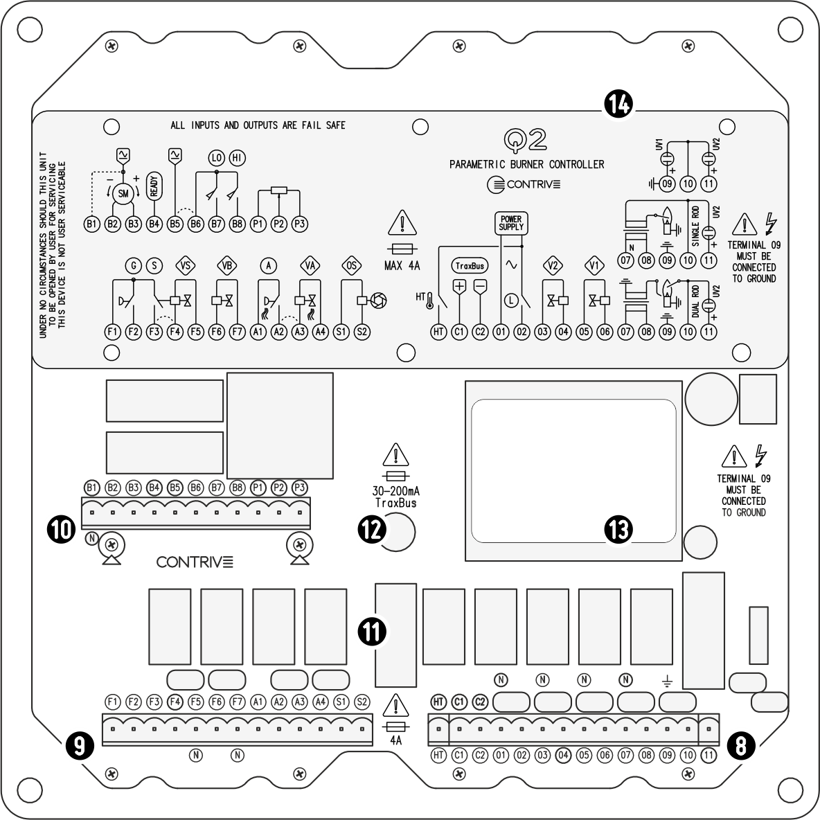
INTERNAL 8 MAIN TERMINAL BOARD 9 EXTENDED TERMINAL BOARD 10 ACTUATOR TERMINAL BOARD 11 POWER SUPPLY FUSE 1 12 TraxBus FUSE 13 IDENTIFICATION LABEL 14 PROTECTIVE COVER
|
||||||||||||||||||||
|
Electrical connections are made through connectors positioned inside the unit; the entire equipment is housed in the upper section and can therefore be replaced easily and quickly when necessary. |
|||||||||||||||||||||
|
OUTPUT INDICATORS [7]
|
|||||||||||||||||||||


|
FRONT VIEW |
Q28 INTERNAL VIEW |