|
BASE ALUMINIUM ALLOY EN AB 46100 |
|
|
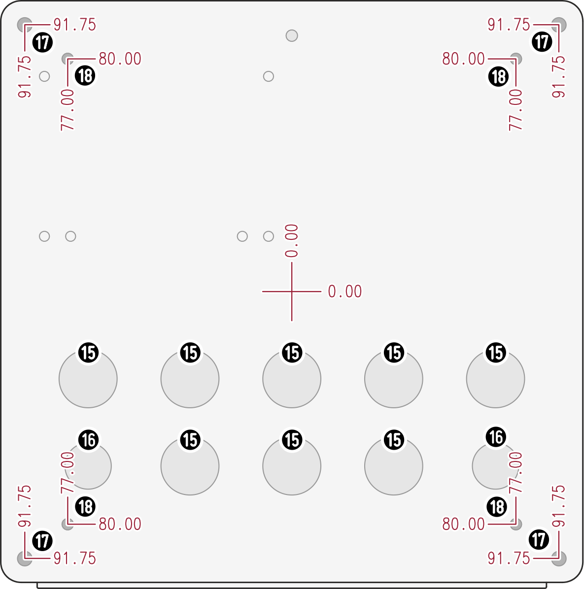
BACK VIEW |
15 Ø 20 mm (8) 16 Ø 16 mm (2) 17 M5 (4) 18 4mm (4) |
|
The device can be fixed using the 4 threaded holes in the base [17] using 4 M5 screws (not supplied), or by opening the 4 pre-drilled holes [18] for M4 screws (not supplied). The positions of the holes for the panel on which the unit sits on are shown in the figure. |
|
|
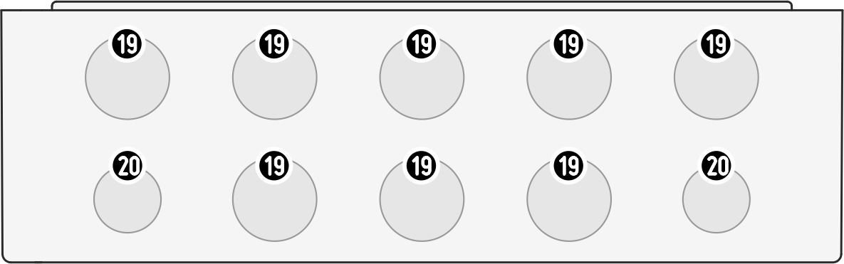
BOTTOM VIEW |
19 M20 x 1,5 (8) 20 M16 x 1,5 (2) |
|
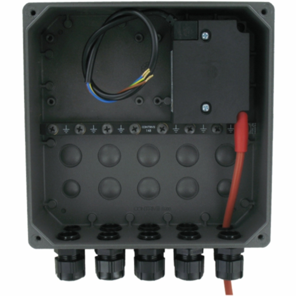
For cable entry there are 10 threaded holes suitable for receiving cable glands, the unused holes must be closed with stoppers, the back side features 8 knockout holes for additional cable exits. According to European Standard EN13611 § 8.2, a minimum protection degree IP40 must be guaranteed, raised to IP54 for open air application. TO ENSURE IP67 IT IS NECESSARY TO USE SPECIFIC CAPS AND CABLE GLANDS STOPPERS:
CABLE GLANDS:
TIGHTENING TORQUES:
|
|
|
|
|
|
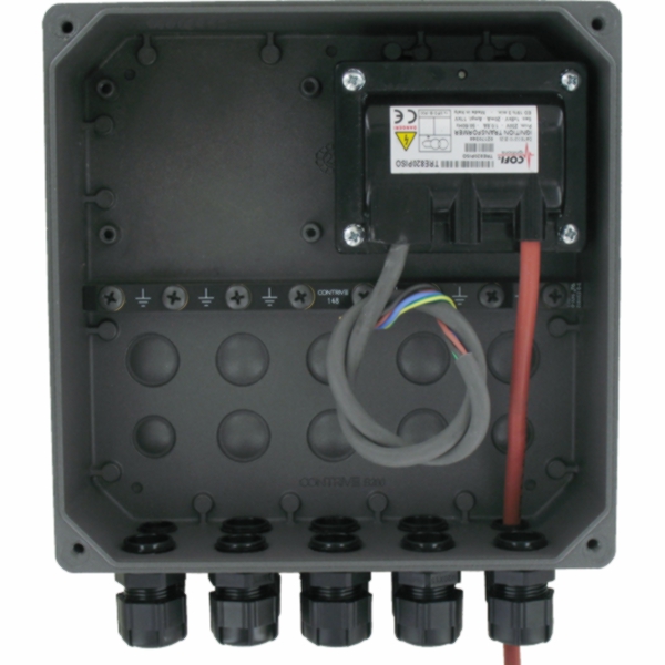
ELECTRONIC IGNITION TRANSFORMER |
INDUCTIVE IGNITION TRANSFORMER |