|
ACTUATOR |
||||||
|
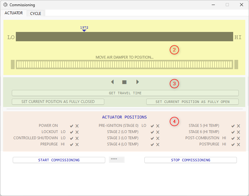
The page relating to the actuator is divided into 3 areas: [2] Current position and manual positioning cursor [3] Control keyboard [4] Setting the position in each stage |
||||||
|
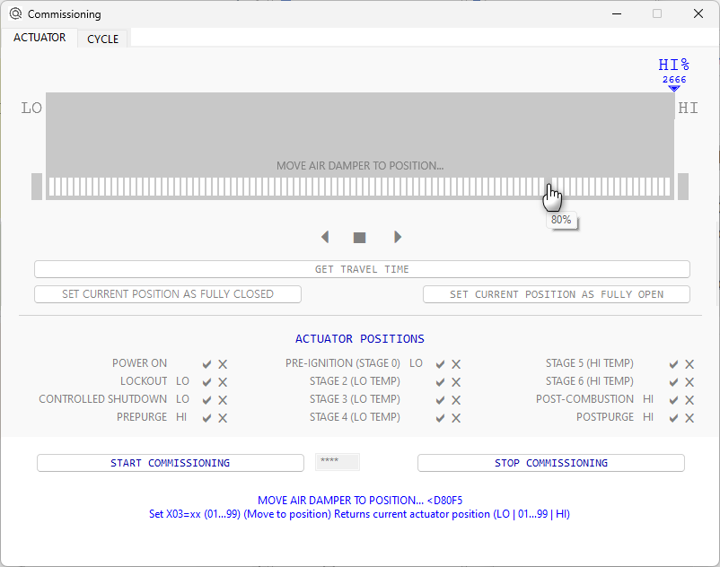
Click on GET TRAVEL TIME to start the acquisition sequence of the actuator characteristics:
|
||||||
|
At the end of the acquisition, it will be possible to move the actuator to the desired position with a click on one of the 98 steps of the scale, the actuator will reach the corresponding value measured by the potentiometer. The two exernal markers correspond to the positions of the LO (0%) and HI (100%) limit switches. Real time position is shown at the top. The three central buttons allow manual movement of the actuator.
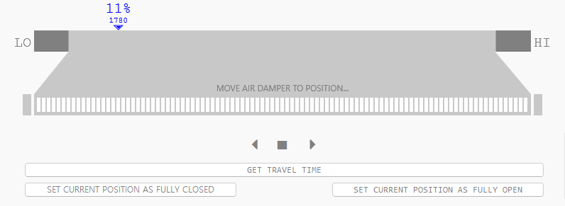
It is possible to restrict the travel of the actuator, once the position you want to assign is manually reached, 1% click on SET CURRENT POSITION AS FULLY CLOSED, in the same way, once you have reached the position you want to assign to 99% click on SET CURRENT POSITION AS FULLY OPEN. |
||||||
|
|
||||||
|
The display highlights that the range 1...99% has been restricted with respect to the limits imposed by the two limit switches, which maintain the 0% and 100% position. These positions can be redefined, the device will recalculate the division each time into 1...99%. |
||||||
|
|
||||||
|
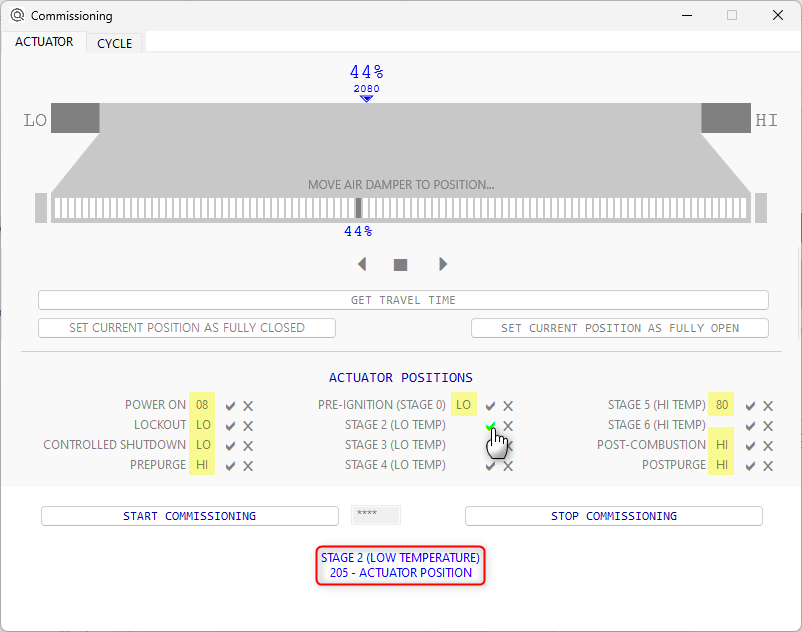
In this phase it is possible to manually position the actuator, and set the current position as the desired one for each stage of the cycle. Since in each stage of the cycle it is possible to preset a position, it will be sufficient to move the actuator to the desired point (in the example in the figure it is 44%) and confirm it for the specific stage (in the example in the figure STAGE 2). The affected parameter is shown at the bottom of the window (red box in the figure). For each stage it is possible to store ˅ or remove x positions. If a position has been assigned it is shown (the ones highlighted in the figure). Upon exiting the COMMISSIONING procedure you will be asked whether to configure these positions into the device. |
QSuite