|
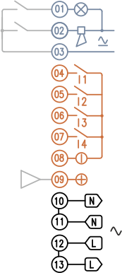
The BLACK terminals are for power supply.
To simplify wiring, there are 2 additional terminals for connections that carry power to Q2.
The ORANGE terminals are for process control.
The functions indicated refer to the device programmed with the default factory configuration.
The 4-20mA analog output can be programmed to control actuators.
There are 2 SPST contacts available at the BLUE terminals.
The functions indicated refer to the device programmed with the default factory configuration.
|
|
|
|
OUTPUTS
|
|
01
|
OUT
|
BURNER ON
|
|
02
|
OUT
|
BURNER LOCKOUT
|
|
03
|
IN
|
COMMON RETURN
|
|
|
|
CONTROL
|
|
04
|
IN
|
THERMOSTAT 1 (BURNER ON/OFF)
|
|
05
|
IN
|
THERMOSTAT 2 (MAIN ON/OFF)
|
|
06
|
IN
|
AIR CONTROL (ON/OFF)
|
|
07
|
IN
|
RESET (UPON RELEASE)
|
|
08
|
OUT
|
COMMON NEGATIVE
|
|
09
|
OUT
|
4...20 mA
|
|
|
|
POWER SUPPLY
|
|
10
|
OUT
|
NEUTRAL
|
|
11
|
IN
|
NEUTRAL
|
|
12
|
OUT
|
PHASE
|
|
13
|
IN
|
PHASE
|
|
With the factory default configuration, each channel is assigned the following functions:
- The burner ignition cycle is started by closing INPUT 1
while opening forces a CONTROLLED SHUTDOWN.
- When the burner is operating, the INPUT 2 controls the main valve
activating and releasing the 2nd stage.
- INPUT 3 controls the air valve output
This control is only effective for stages where it is permitted.
- INPUT 4 allows remote UNLOCKing of the burner and must be activated for at least 1 second.
- Reset occurs when the input is released.
- OUTPUT 1 activates when the burner is RUNNING.
- OUTPUT 2 activates while the burner is in LOCKOUT.
- When a 4..20mA current loop is connected to the analog output, the relative indicator lights up.
The span is adjustable with the multi-turn trimmer [4]
The USB connector [3] allows connection to a PC for any WiFi settings.
Expert users can also modify the factory default operating rules.
|

|
It is advisable to activate TIMEOUT B05 so that in case of absence of Qio control the device goes into lockout (while the burner is on).
|
|
|