|
TRADITIONAL ELECTRICAL CONTROL |
||||||||||||||||||||||||||
|
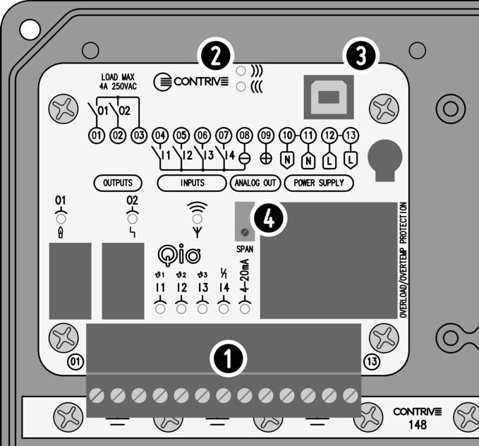
Remote control of Q2 can be achieved with traditional electrical signals. The easiest way is to control the power supply directly, the contact of a switch or relay will power the device that will start the ignition cycle of the burner (if it was turned off while it was in lockout, the next time it is turned on it will still be in the same lockout). Full traditional control with electrical signals can be achieved with the optional Qio board which is installed in the base of the device. Communication with Q2 occurs via the optical interface [2] that faces the corresponding one on the Q2 board, operation is guaranteed only when the front part is correctly positioned on the base. |
||||||||||||||||||||||||||
|
|
1 TERMINAL BOARD 2 OPTICAL INTERFACE 3 USB-B CONNECTOR 4 LOOP CURRENT ADJUST |
|||||||||||||||||||||||||
|
INDICATORS
|
||||||||||||||||||||||||||
|
With the factory default configuration, each channel is assigned the following functions: The burner ignition cycle is started by closing the contact at input 1, while opening forces a CONTROLLED SHUTDOWN. When the burner is operating, the contact at input 2 controls the main valve, activating and releasing the 2nd stage. Input 3 controls the air valve output. Input 4 allows remote unlocking of the burner and must be activated for at least 1 second, reset occurs when the input is released. Output 1 activates when the burner is RUNNING. When a 4..20mA current loop is connected to the analog output, the relative indicator lights up. |
||||||||||||||||||||||||||
|
The USB connector [3] allows connection to a PC for any WiFi settings. |
||||||||||||||||||||||||||
Q2