|
STAGE 2 |
|
|
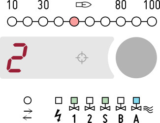
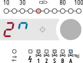
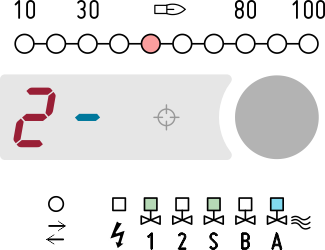
This is the first stage reached after the ignition for burners operating in low temperature mode (HT input off). For direct ignition – single stage – burners, this is the only operating stage which will therefore be set as continuous. For multi-stage burners it is possible to set the duration of this stage which usually corresponds to the operation of the pilot burner only, after which stage 3 begins. |
|
|
The behaviour of all fuel valves and the air valve can be defined. |
|
|
The actuator position can be preset and even changed remotely. The air pressure switch can be enabled to detect air failure or air simulation, depending on air output setting. The fuel pressure switch can be enabled to detect fuel failure. Response times of the air and fuel pressure switches are adjustable to tolerate short drops or spikes. |
|
|
The presence of flame is detected by one or both sensors (in this case it will most likely be the only sensor that detects the flame which could also be the only one installed). The reaction time to the flame loss can be set. |
|
|
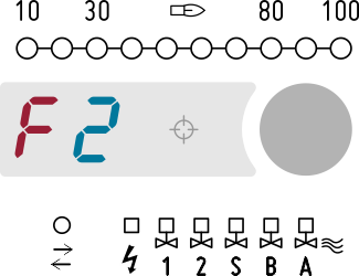
If enabled, the electro-optical shutter periodically checks the correct operation of the UV sensor. Specific parameters define the behaviour in the event of flame quench, fuel pressure failure and air pressure failure: • lockout • re-ignition • recycle from the beginning |
|
|
If necessary, the post-combustion and post-purge stages will be performed before. |
|
|
This stage can be terminated by: • manual shutdown • controlled shutdown • lockout The transition to another low temperature stage can be requested with remote control. The transition to high temperature mode (stage 5) can take place immediately upon activation of the HT input or at next burner restart, according to parameter G08. |
|
|
It is also possible to define a minimum duration during which any controlled shutdown requests are ignored (for example to avoid too short operating periods in burners with impulse regulation. |
|
|
Allowed remote commands H R S s A a O o f L D d Dxx
3 4 |
|
Q2