|
OIL BURNERS |
|||||||||||||||||||||||||||||
|
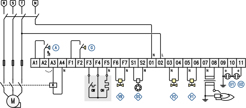
Oil burners are designed to burn various types of liquid fuels including heavy oil, light oil and even waste oil and are suitable in applications where a constant heat output is required for extended periods. This is the Q2 terminal block for an oil burner and below is a wiring diagram for a typical application. |
|||||||||||||||||||||||||||||
|
|
|||||||||||||||||||||||||||||
|
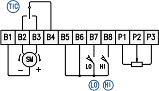
At the start of the cycle, the air simulation test is performed to check the efficiency of the pressure switch A 1 connected to the A1-A2 terminals before proceeding with the activation of the OH preheater connected to the F4-F5 terminals. Once the fuel temperature has been reached, the thermostat WH inside the pre-heater will activate the input at terminal F3 and the motor controlled by the VA output at terminals A3-A4 will start. When the pressure switch A detects the air pressure, the pre-purge time starts. Usually in this stage the ignition transformer is activated to burn any oil leaks and consequently detect the presence of unwanted flames. After having detected the correct fuel pressure by means of the pressure switch at terminals F1-F2 and having verified the activation of the ignitor output, the selected valves will activate (normally the valve V1 connected to terminals 05-06). If a valid flame signal is detected within the programmed safety time, the valve is kept open: the burner is on. If no flame is detected there will be a lockout (up to 3 further ignition attempts can be defined before lockout 2). For any subsequent stages it will be possible to define which valves must be active (typically the second stage valve V2 connected to terminals 03-04 with the possibility of intermittent or interrupted operation for V1). The multifunction valve VB (terminals F6-F7) can be configured as a return valve or as a further stage. In the event of a flame failure during operation, it is possible to set an immediate re-ignition 2, a complete recycle from the beginning or a lockout. After a lockout or a shutdown request, a post-combustion time is allowed, possibly followed by post-purging. For flame detection, one or two (if independent supervision of 2 flames is required) UV sensors are used, which can be equipped with electro-optical shutters in case of permanent use. If the temperature of the combustion chamber walls exceeds 750°C it will be possible to exclude the direct flame surveillance by activating the HT input with a signal coming from a safety thermoregulator. Reset from lockout can be done with a front button or with a remote control. To put the burner out of service (manual shutdown) press the button on the front panel during the operating cycle. For modulating burners, it is possible to control the air damper servomotor by forcing it to the maximum flow rate for ventilation and minimum for ignition. If it is equipped with a potentiometer, it will also be possible to control its position with remote commands, alternatively the control can be obtained with a traditional thermoregulator (TIC) which receives consent from terminal B4, which excludes it during the ventilation or ignition stages.
|
|||||||||||||||||||||||||||||
|
|
|||||||||||||||||||||||||||||
|
|
||||||||||||||||||||||||||||
|
|
|||||||||||||||||||||||||||||
Q2