|
MZ4 - 3 POINTS ACTUATOR |
|
|
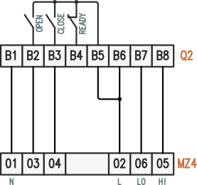
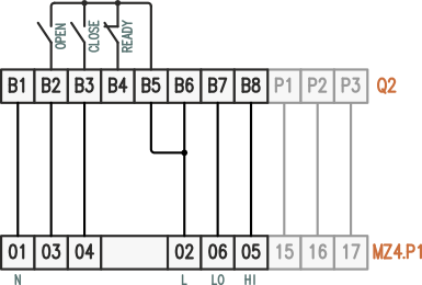
In this configuration, the 3-point actuator is fully controlled by the Q2 unit, which determines the actuator position at each stage of the operating cycle. Except for the ventilation and ignition phases, the position can also be managed via fieldbus during all other operating stages. |
|
|
|
|
|
Elektrogas MZ4 Wiring diagram for full position control via Q2 unit |
Elektrogas MZ4.P1 Potentiometer enables management of any intermediate position between limit switches |
|
Adjustment and Parameter Configuration:
For other operating stages (S03, L02, C04, 205, 305, 405, 505, 605, Y03), specific positions can be defined, or the actuator can remain in its current position (default). Remote control is always available during these stages. Recommended Procedure For a quick setup, it is recommended to use the Commissioning utility in QSuite. This tool automatically scans the mechanical limits (limit switches) and the travel time; optionally, it allows for the definition of preferred positions for the various operating stages. External temperature controller If the actuator position is managed by an external temperature controller (TIC), refer to the wiring diagram provided at the beginning of the chapter. |
|
Q2