|
MONITOR ONLY |
|
|
|
|
|
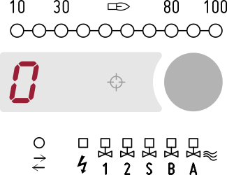
The device can be configured to be used as a dual channel flame relay suitable for permanent operation (parameter S01 - Power-on behaviour). The display shows 0 when no flame is detected. |
|
|
|
|
|
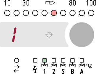
Output V1 (terminal 6) is activated when the presence of flame is detected by the sensor connected to input 2 (terminal 10). The display shows 1 when only the sensor connected to input 1 detects flame. |
|
|
|
|
|
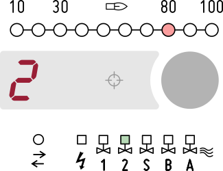
Output V2 (terminal 4) is activated when the presence of flame is detected by the sensor connected to input 2 (terminal 11). The display shows 2 when only the sensor connected to input 2 detects flame. |
|
|
|
|
|
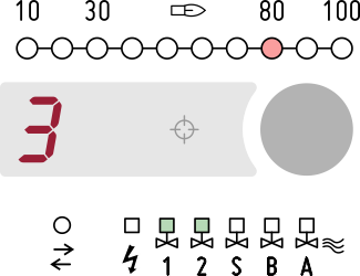
The display shows 3 when both sensors detect flame. The bargraph shows the flame signal according to the settings of parameter G06 (Flame signal display). If enabled, the electro-optical shutter periodically checks the correct operation of the UV sensors (parameter G07 - Electro-optical shutter). |
|
|
Allowed remote commands S s A a O o L |
|