|
LEAKAGE RATE |
||||||||||||||||||||||||||||||||||||||||||||||||||||||||||||||||||||||||||||||||||||||||||||||||||||||||||
|
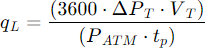
According the EN 1643 standard the system shall prevent the opening of the valves when the leakage rate exceeds 0,1% of the burner heat input, starting over 50 dm3/h. Recommended max leakage ≤ 200 dm3/h Example: With a burner capacity of 100 m3/h, the maximum leakage rate is 100 dm3/h. If the burner capacity is 30 m3/h, the maximum leakage rate would be 50 dm3/h. The effective leakage rate in dm3/h is given from the following equation (EN 13611):
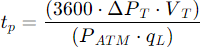
From the above equation we can derive the duration of the fill test and empty test periods required to detect the maximum permissible leakage:
The total duration of the test is 2 ∙ to + 2 ∙ tp Test volume Test volume VT consists of inner volume of outlet chamber of upstream valve + inlet chamber of all downstream valves + pipework volume. The table shows the internal volumes of the valves1 and the volume for each meter of pipe referred to different nominal diameters.
Set 10 seconds for fill and empty test periods (T03 T05 T12 T15) and pressure switch threshold at 50 mbar. The Q2 device simplifies installation by integrating both leakage control and minimum pressure detection into a single pressure switch. If you wish to set the pressure switch to a value other than 0,5∙Pu for minimum pressure intervention, you simply need to differentiate the test times:
The following coefficients should be applied to compensate for variations in the pressure switch intervention threshold:
Times are expressed as percentages relative to the reference time for a standard 50% calibration. Practical Example If previous calculations resulted in 10 seconds with Pu = 200 mbar:
The total test time (excluding filling and emptying phases) always remains 20 seconds. Notes: - the upward tripping point of a pressure switch is slightly different from the downward one. - minimum time that can be set in Q2 is 5 seconds. |
||||||||||||||||||||||||||||||||||||||||||||||||||||||||||||||||||||||||||||||||||||||||||||||||||||||||||
|
A utility for calculating test times is available in the Q.Suite software |
||||||||||||||||||||||||||||||||||||||||||||||||||||||||||||||||||||||||||||||||||||||||||||||||||||||||||
|
|
||||||||||||||||||||||||||||||||||||||||||||||||||||||||||||||||||||||||||||||||||||||||||||||||||||||||||
Q2