|
GENERAL DEVICE RELATED SETTINGS |
|
|
|
G00 – PASSWORD Password to access configuration and commissioning environment. - 4 to 8 alphanumeric characters (DEFAULT 00000000) At first setup you will be asked to change the password. EN298 § 7.101.3.1 |
|
|
G01 – ACTUATOR MAX TRAVEL TIME Time required by the actuator to complete the full travel: - disabled (default) This time is automatically acquired by the device during the commissioning. Specific fault will be shown if the actuator takes longer. |
|
|
G02 – ACTUATOR 1% POSITION Position detected by the potentiometer as fully closed of the actuator. - 0 … 4095 bit This position is automatically acquired by the device during the commissioning. EN298 § 7.101.2.6 |
|
|
G03 – ACTUATOR 99% POSITION Position detected by the potentiometer as fully open of the actuator. - 0 … 4095 bit This position is automatically acquired by the device during the commissioning. EN298 § 7.101.2.6 |
|
|
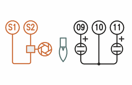
G04 – FLAME 1 SENSITIVITY The minimum flame signal detectable by the sensor connected to input 1 (terminal 10) can be either a UV sensor or an electrode. - 1 … 9 µA (DEFAULT 2 µA) |
|
|
G05 – FLAME 2 SENSITIVITY The minimum flame signal detectable by the UV sensor connected to input 2 (terminal 11). - 1 … 9 µA (DEFAULT 2 µA) |
|
|
G06 – FLAME SIGNAL DISPLAY Flame signal that will be displayed by the bargraph: - SENSOR 1 EN298 § 3.107 |
|
|
G07 – ELECTRO OPTICAL SHUTTER When a UV sensor is used and permanent operation of the burner is required it will be necessary to place an electro-optical shutter in front of the sensor, set to which sensor it has been fitted: - INACTIVE (DEFAULT) This device will be activated periodically to verify the reaction of the sensor to flame quenching. EN298 § 7.101.4.1.2 – § 7.101.4.1.5 |
|
|
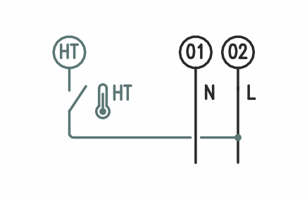
G08 – HIGH TEMPERATURE The high temperature input at the HT terminal allows activation of the indirect surveillance of the flame. The signal must come from a safety thermoregulator which is activated when the walls of the combustion chamber exceed the auto-ignition temperature of the fuel. As long as this signal is present, the flame sensors will be excluded: - IMMEDIATE (DEFAULT) EN 13577-2 § 4.10.3 |
|
|
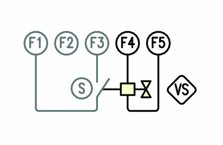
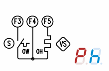
G09 – PROOF OF CLOSURE SWITCH RESPONSE TIME The VS fuel valve connected to terminal F4 can be equipped with a limit switch to check its physical position. This parameter allows you to define the time within which the limit switch contact must be detected as closed after the VS valve has been activated: - 1 … 10 seconds (DEFAULT 1) When the valve is not equipped with the "proof of closure switch", it will be necessary to read the output status directly by connecting the terminal F3 to terminal F4. NFPA85 – NFPA86 § 3.3.69.7 – EN13577-2 § 4.3.6 – ISO23511-1 G09 – OIL PREHEATING TIME For the oil burner, the fuel heater is connected to terminal F4 and the associated thermostat must give consent to terminal F3 within the maximum time of 10 minutes, otherwise there will be a lockout. Select this option only if the burner is equipped with a fuel heater. - OIL HEATER |
Q2