|
FUEL PRESSURE SWITCHES |
|
|
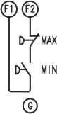
The minimum fuel pressure switch is connected to terminals F1-F2. This single minimum pressure switch is also used by the valves proving function, if enabled. This means that the minimum pressure intervention will take place at 1/2 of the nominal pressure, because this is the setting required for the correct operation of the tightness control. |
|
|
|
If there is a pressure switch that detects excessive fuel pressure (EN 13577-2 § 4.3.5), it will be connected in series as shown in the figure. |
|
The monitoring of the gas pressure switch can be disabled or enabled in each stage (EN 13577-2 § 4.3.4 and § 4.3.5), also setting the response time to compensate for delays in the formation of the correct pressure or unwanted interventions due to vibrations or other accidental phenomena. POSITIONING Standard EN ISO 13577-2 § 4.3.4 and § 4.3.5 requires that gas pressure switches ensure reliable pressure detection without prescribing a specific positioning relative to the valves. Q2 features the pressure switch downstream of the main safety valve and upstream of the burner valves, ensuring:
This configuration is fully compliant with the requirements of standard ISO 13577-4:2022. |
|
|
|
The pressure switch that detects the minimum gas pressure must always be installed downstream of the VS valve. |
|
WAIT BEFORE IGNITION This input can also temporarily suspend the cycle while waiting for an external signal. |
|
|
|
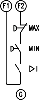
For example, if the actuator is controlled externally, it is essential to wait for it to reach the required closed position before proceeding with ignition (I contact). The FUEL PRESSURE RESPONSE TIME must be set to a value greater than the time required for the actuator to travel. If pressure switches are present, they will be connected in series. The I contact must be kept closed in all phases in which the fuel pressure switch check is active. The most correct method is the one illustrated in CENTRALIZED ACTUATOR. |
Q2