|
WEBSERVER |
|
|
From any browser you can access the web server embedded in Qnet by specifying as URL the IP address assigned to the device. Supports up to 4 clients connected simultaneously, performance may degrade as the number of connected clients increases Select your preferred language, then press CONTINUE . |
|
|
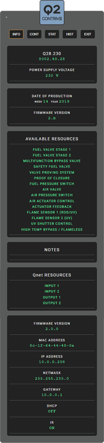
After logging in, the page containing general information will be displayed, which can be called up and updated every time you press the INFO button. The first box shows the model and the supply voltage. The second box contains the manufacturing date and firmware version of the device. AVAILABLE RESOURCES List of resources available for the specific Q2 model.. NOTES Q2 may contain production notes or information on any repair work. Qnet RESOURCES List of resources available for Qnet. CURRENT Qnet SETTINGS Firmware version MAC address Subnet mask Gateway DHCP mode IR interface (Q2) . |
|
|
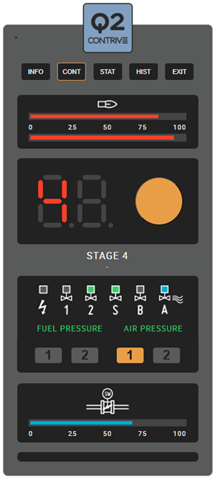
By clicking on the CONT button you go to the control page which shows the operating status of the burner. FLAME SIGNAL The first box shows the intensity of the flame signal for the two inputs. The symbol changes if the High Temperature mode is active. STATUS DISPLAY Replicates the display on the device that indicates the cycle status or the lockout. Click on the button to reset a burner from lockout. INDICATORS For each Q2 output there is a status indicator that replicates those present on the device. The status of the fuel and air pressure switches is also reported, followed by the status of the Qnet general purpose digital inputs and outputs. ACTUATOR Actuator opening percentage indicator. |
|
|
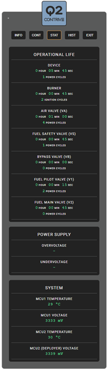
Clicking on the STAT button takes you to the page relating to the operating statistics. Total operating time and the times the DEVICE was powered. Total operating time (flame present) and how many ignition cycles were made by the BURNER. Total operating time and how many power cycles were made by the AIR VALVE. Total operating time and how many power cycles were made by the FUEL SAFETY VALVE. Total operating time and how many power cycles were made by the BYPASS VALVE. Total operating time and how many power cycles were made by the PILOT VALVE. Total operating time and how many power cycles were made by the MAIN VALVE. Any OVERVOLTAGE or UNDERVOLTAGE values that caused a lockout. Current supply VOLTAGE and TEMPERATURE of the two microprocessors. |
|
|
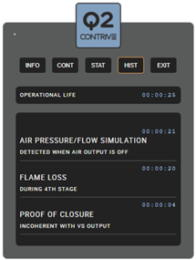
By clicking on the HIST button you access the page containing the history of the last 39 lockouts. For all events, the TIME in which they occurred is reported, referring to the operational life of the device, which is reported in the first box. For each lockout event, there is a DESCRIPTION of the cause and any details. |
|
Q2